You want more? Thanks for sticking with me!
The decal also came without the dimensions, and that is what I used to put on my cabinet front, after I laminated it of course!
Here are some pictures of what we have so far...You can see the switches are in, as is the connection for the speaker/headphones (high impedance), lower left under the first switch on the left, and the two position switch, under the second switch left side, the ground connector upper left, and the antenna connections upper right.
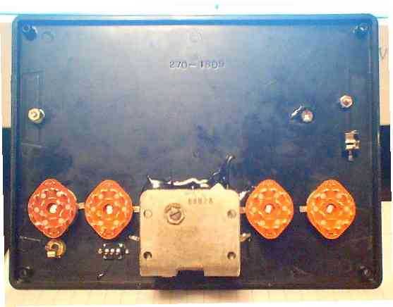
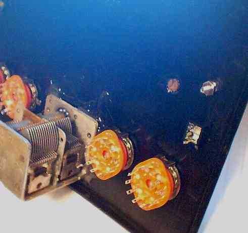
You can see the antenna connections better on the second view. Also note the backside of the trimmer cap. This cap is nice for reducing some of the strong signals around here on AM BC bands. Also helps with selectivity. I put a pigtail like connector leading from the small screw in series with the Fahnstock clip and the 1/8th inch antenna female jack. Note the typical 2 ganged tuning capacitor. This one is probably in your "junk box" as we speak. It is out of an old Zenith, first part is 30-156pF, second is 40-460pF. This one had a 3/8ths inch drive, so I had to modify my Radio Shack knob to fit. I "bored it out" with my handy dandy Dremel tool. I am finding more and more needs for that tool.
Next I had to wire the coils to the switches. This is where it actually got interesting. On the far right switch is the antenna coils (smaller primary coils) on the second from the right is the tuner or inductor coils. The idea is to connect each end of the coil to the corresponding circuit of the switch. Here is a schematic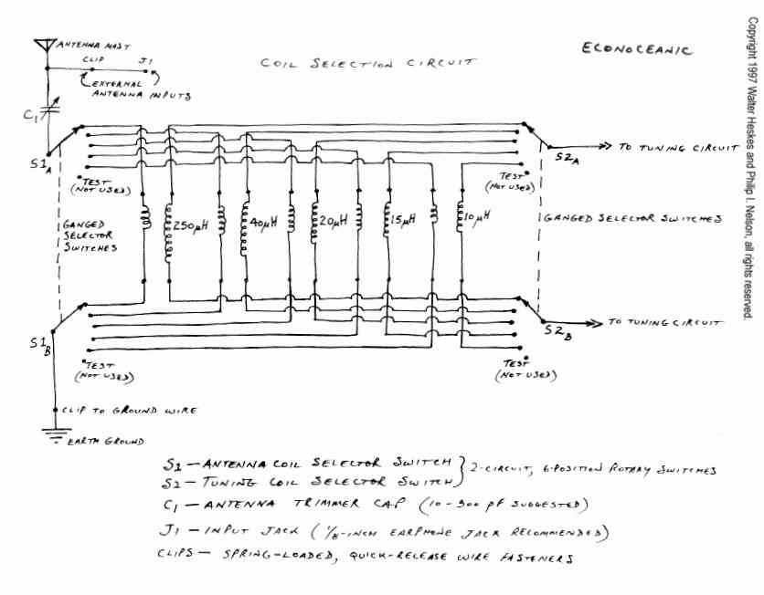
You get the idea?
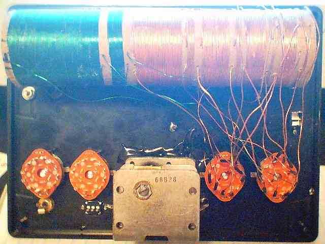
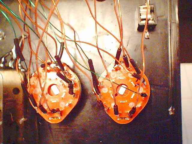
Here is a picture after I connected the antenna coils and the inductors too. And here is a closer view. The switches have 2 conections associated with each circuit. (That makes sense) You connect each coil end, antenna and ground, to the circuits. On these switches, each end of the circuit is directly opposite (180 degrees) of the other side and the connection is in the middle. I put a small "cap" of 20 guage wire covering over the ends of the wires to minimize shorts. Notice the "hap-hazzard look"? Well, Water Heskes noted that right angle bends would decrease sensitivity.
Ok? Still with me? Want to see more?
Click here to continue, click here to return to my radio pages
send Tom Dufresne an
e-mail!