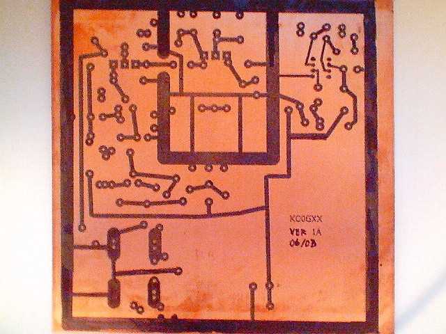
 Notice the black areas. They become the copper traces
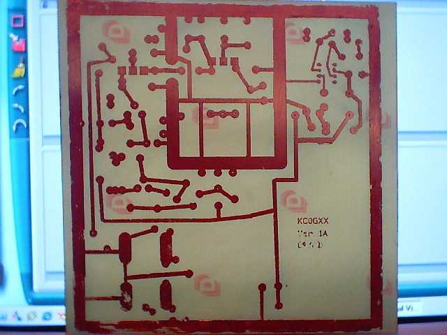 a) Now you can see the copper areas all gone, except where the black areas were. These become the traces!
Allow me to take you through this rigs life.
1) Found design in book, maybe three years ago
2) Finally got all components together-found inductor at Surplus Supply House in Nebraska (unfortunately, it was too big but that is another story....)
3) Designed and burned PCB from scratch. I merely took the "ghost" image they had in the book and made a close copy in a program for schematics-its called Circad . After I had the design, I went over it a million times to assure I had all the traces and leads and tracks correct.
I then printed the design on standard paper with a laser printer, in reverse. Next, I copied the design on clear acetate "overhead" sheets. Make a few, not just one acetate. I had to do it a few times to get the traces just right, and the density on the acetate as sharp as possible. Now, I had to transfer the design on to the copper PCB. That was probably the hardest part of the process. You need to get a real hot iron (old ones seem to be real good for this- NOT your wifes' best iron, TRUST ME!!)
Put a sheet of paper over the acetate sheet, center the design over the PCB, then press the hot iron over the paper/acetate sandwich. It takes about 5 minutes to do it right-keep the iron moving or you will melt the acetate or scorch the paper. The "ink" from the laser is transferred onto the PCB, and you carefully "peel" the sandwich off. If the traces are all clear, immediately cool the PCB in cold water to set the "ink".
If all the traces are sharply defined, good! If not, you can "touch them up" if needed with a "Sharpie" permanent ink marking pen. If they are too messy or broken up badly, just wash the board with acetone and re-do the acetate sandwich. I make several of the acetate sheets just in case!
Notice the black areas. They become the copper tracesa) Now you can see the copper areas all gone, except where the black areas were. These become the traces!
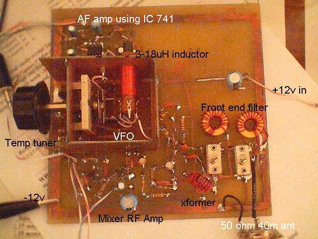
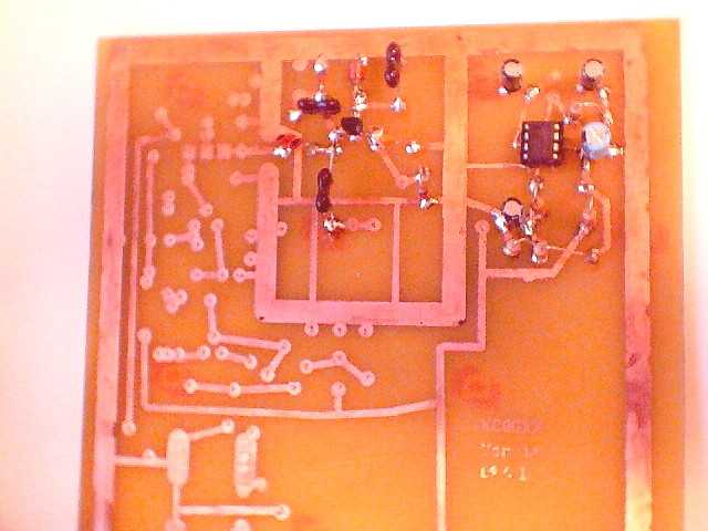 b) Now you start to populate the board.
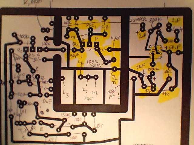 I checked off components on a paper copy of the PCB as I mounted them on the real one.
5) No audio at all from the AF amp, although it did "hummm" when I put a finger on one of the caps. And why were the electrolytic capacitors so hot? They swelled and popped. That's not good...So, I trouble shot... And trouble shot... and trouble shot until my trouble shooter was sore. Then I actually took the board to a ham meeting here in town. (I brought my 2N2222 40 meter homebrew transceiver so I wouldn't feel too badly) They looked at the receiver, and everyone had an idea. Mike Smith, NŘXY decided that I had put my electrolytics bas-ackwards. How did I do that? Ohhh wow, I remember now, the black band is the NEGATIVE SIDE TOM!!! OOOPS!!!!
6) Well, after kicking myself in the butt a bit everyone looked at my 2N2-40 HB and pronounced it beautiful-a small concession to a rather painful day! ;0 (Mike actually spared me-he told me in an aside that the caps were bas-ackwards;thanks Mike :)
7) After I switched out all the caps, I checked all the transistors for damage (all three of 'em, a real chore) I started again. Still no CW, although I did notice no heat in the caps. What to do? Well, after the last round of troubleshooting, I just gave up for awhile. That was around 05/03.
Recently (11/03, Ron Cerkoney (NŘRC) posted a notice on the QRP reflector. He said he wanted to "give something back" to amateur radio, so I took him up on the deal. He agreed to take a look at the receiver, so I shipped it to him. He wrote back right away and said he fixed a problem with some busted traces on the AF amp (Manhattan style!), and oh, BTW, he said, your inductor is about 1000 times too big! You have about a 9 mH slugged tuned inductor, and you need a 5uH inductor! Hmmm. So, he sent it back, and with his blessing and help I was to "march on" and ask Ron if I needed him.
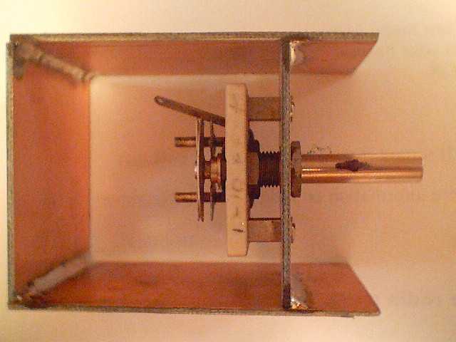
8) Ron got me back on track, and after three or four months of inactivity, I started looking for the new slugged tuned coil. Well, I found one at Surplus Sales of Nebraska.It was a 3-19uH coil, but it was close enough for me! I needed a coil that was "nominally" 4.5uH's, so I figured it would work. Well, I had to back the slug practically all the way out (check out the pictures of the inductor) but I got a good clear signal from the VFO. This time here was no doubt, the VFO blew my ears off this time, tuning from 7.000mHz to 7.070mHz. I was a little disappointed, I expected a slightly bigger range. The book said I could expect about 200kHz. I had 70 kHz. Well, another day I suppose....
9) I went back to my desk, hooked everything up. I used a combination of two Radio Shack mini-amplifier speakers (#277-1008C) hooked up in series. Quite an amplifier, and ......Nothing! :( Still no CW. In almost pure frustration (or blind luck, I am not sure which) I patched the antenna input directly through, by-passing the front end filter completely. There she was! Clear, pure CW.
It was great! I could tune it, hear it clear as a bell. Nice to hear as anyone who has built a homebrew receiver will attest, there is nothing quite like those first notes of CW over a homebrew you build yourself. Success! Naturally, after the "glow" faded, I still had a few things to check. Why did I need the "super amp" set up? (As it turned out a trace had busted from the final electrolytic cap to the AF output. SOLVED!) What was the matter with the front end filter? (too many turns on the first torroid inductor. I took off three turns. SOLVED!) Why do I only have 70 kHz of "bandspread? Well that one is not so easy for me. I have heard that I may have some "stray inductance" that may be causing that; not real sure how to solve that one. More trouble shooting?
10) Now, the only thing left I need to do is maybe mount the unit in a nice box, and maybe even see if I can get a "filter" for CW. I am amazed at the sensitivity, I have bonafide contacts via e-mail ham SWL. I asked if the hams could confirm that I heard them calling CQ or whatever at so-and-so time, etc. Hey, maybe I can rig up some kind of a counter so I don't need my portable Radio Shack frequency counter. I can come within a few kilohertz or so with that! Whats next? Maybe another DC receiver, this one is on 80 meters!